YML Magnetic Receiver Loop Kit

SUMMARY#
The YooFab YML Active Magnetic Receiver Loop, also known as YooLoop, is a high-end active magnetic receiver loop designed for the 1Mhz to 30Mhz frequency range. Ideal for areas with limited space and high noise levels, it offers superior reception by focusing on the magnetic component of radio signals.
In an era where man-made noise is increasingly interfering with radio signals, the YooFab YML stands out by offering a directional, magnetic component-focused solution. Its design ensures optimal reception with minimal noise, making it an excellent choice for urban settings and small spaces.
CHOICE#
You are free to choose how you would like to power your YooFab Active Magnetic Receiver Loop. The options include:
- A 9 volt battery (PP3) connector. The battery is located in the metal housing.
- The shop also offers a 9 Volt AAA battery pack. This is similarly located within the metal housing.
WHAT IS INCLUDED IN YOUR KIT:#
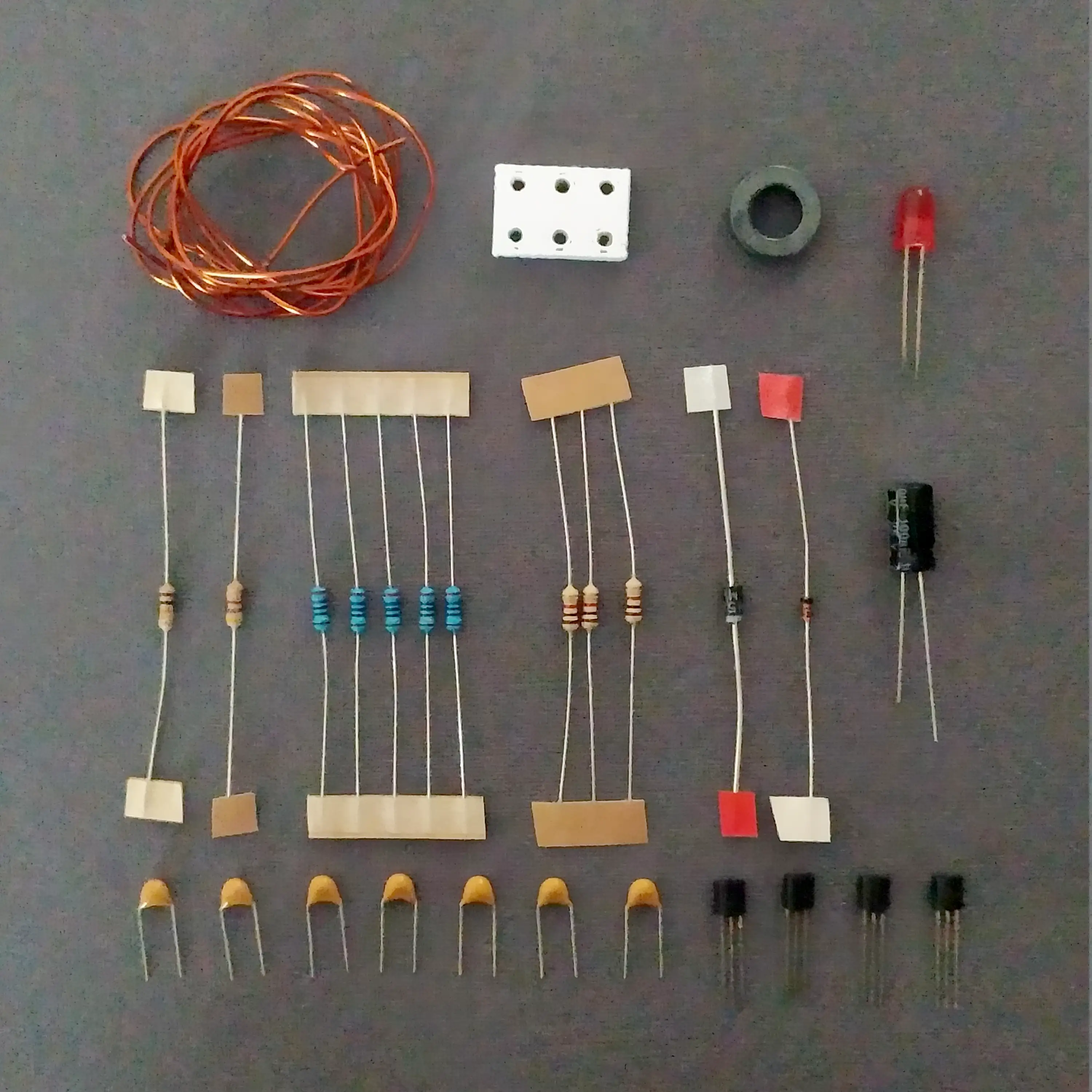
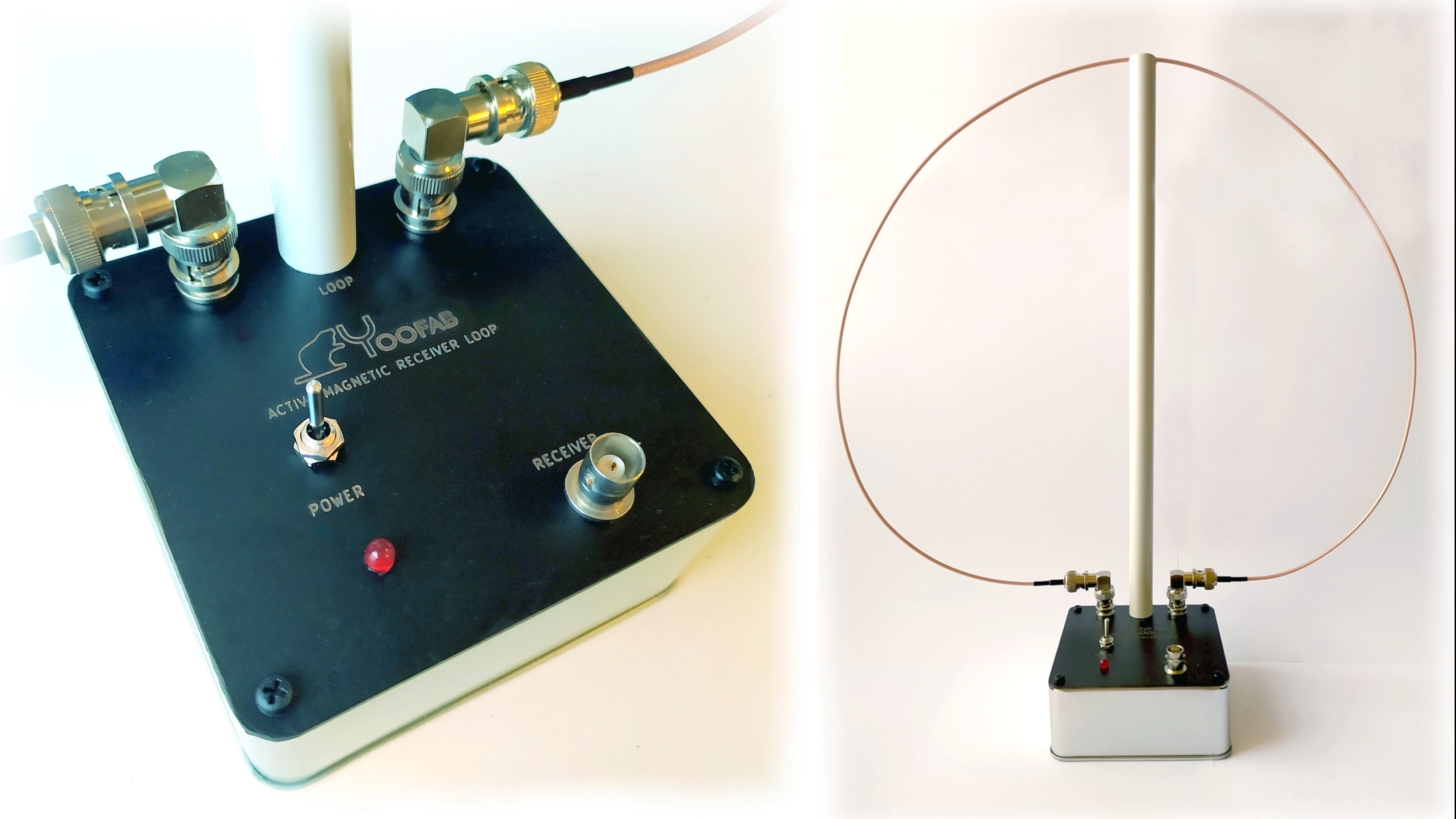
- PCB, with black solder resist, white silk screen, all holes drilled; it serves as both the front panel and the place to solder components.
- All required electronics components
- Hardware, such as metal standoff posts, BNC connectors, Right angle BNC adaptors, Power switch, Screws
- Approximately 100 × 100 mm anodised steel enclosure.
- One meter of
RG316DCoax Cable (with BNC plugs already soldered), where the outer sheath is used as the loop

ADVANTAGES AND NOISE REJECTION MECHANISM:#
Differential Amplification: By amplifying the difference between the signals at the loop's ends, the amplifier inherently rejects common-mode noise, including much of the ambient electrical noise that does not induce a differential signal in the loop. This property is particularly effective against symmetrically distributed noise sources.
Impedance Matching: The design employs careful attention to impedance matching throughout the signal path, from the loop through the amplifier and out to the coaxial cable. This minimizes reflections and transmission losses, which can further degrade the signal-to-noise ratio.
Magnetic Field Sensitivity: The loop's primary sensitivity to magnetic fields means it's inherently less responsive to electric field noise. This characteristic, combined with your low-noise amplification strategy, ensures that the aerial system is particularly effective at receiving the intended signals while rejecting electric field-based interference.
Directivity: The physical orientation of the loop can be adjusted to null out interference from specific directions, exploiting the loop's directional reception pattern to further reduce noise.
The design exemplifies a sophisticated approach to aerial design, focusing on noise rejection and signal integrity through careful circuit design rather than relying solely on the aerial's physical properties. This approach allows for a broader operational bandwidth and versatility in handling various noise environments, particularly in densely populated or electrically noisy areas where traditional high Q magnetic loops might be less effective or more cumbersome to tune.
KEY FEATURES:#
- Frequency Range: 1Mhz to 30Mhz, covering long, medium, and shortwave bands.
- Noise Immunity: Specifically targets the magnetic component of radio signals, reducing man-made noise interference.
- Directional Sensitivity: Enhances signal reception by orienting the loop towards the station.
- Ease of Use: No manual tuning required; built with weather-resistant materials for indoor/outdoor use.
- Versatility: Performs well even near common RF noise sources, demonstrating the YooFab YML design superiority.
KEY COMPONENTS OF THE YOOFAB / M0OOZ DESIGN:#
The 1-Meter-Long Loop: is a practical solution for a diverse range of frequencies, particularly effective in frequency bands ranging from 3.5 to 14 MHz. The small physical size of the loop in relation to the wavelength enables it to effectively interact with the magnetic component of the electromagnetic field, without the need for extensive wire lengths required for a traditional aerial.
Low Z Differential Amplifier: This design choice is crucial for effectively capturing the magnetic field variations across the loop with minimal loss and noise introduction. A low impedance differential amplifier ensures that the small voltages induced in the loop by magnetic fields are amplified without significantly adding to the noise floor.
Emitter Followers for Buffering: By using emitter followers on both sides of the differential amplifier, we ensure a low output impedance, which is ideal for driving subsequent stages like the balun and maintaining signal integrity without significant distortion or loss.
Balun for Coaxial Cable Coupling: The balun (balanced to unbalanced transformer) is essential for converting the balanced output from your emitter followers to an unbalanced signal suitable for a coaxial cable. This not only aids in preserving the signal quality, but also in minimizing potential interference and losses as the signal is transmitted to a receiver.
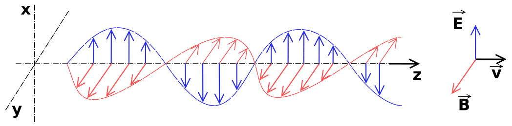
UNDERSTANDING RADIO SIGNALS#
Radio signals consist of both electrical and magnetic components. The YooFab YML innovative design focuses on the magnetic aspect, offering several advantages:
- Reduced Noise: Unlike electrical aerials, the YooFab YML is less prone to absorbing noise from electrical appliances.
- Directional Reception: By capturing the magnetic component, the YooFab YML can be directed for best reception or to avoid interference.
COMPONENTS AND ASSEMBLY#
The YooFab Active Magnetic Receiver Loop Kit includes:
- Sensitive HF aerial: Operates primarily in the magnetic domain for effective HF spectrum coverage.
- Power Supply: You could use a PP3 battery, or better choose the YooFab AAA 9 Volt battery pack available from the Shop. 2
- Electrical QRM Immunity: Ideal for urban environments, offering a discreet and effective reception solution.
- More information on Magnetism: You can find more content on Magnetism here.
- Toroid winding: An extensive article on this subject can be found here
IMPORTANT NOTES#
- Receive-Only: The YooFab YML is designed solely for receiving; transmitting is not supported. Please remember this if you connect the loop to a transceiver. Pressing PTT will probably fry your transmitter and will certainly toast the electronics in the loop amplifier.
- Design and Placement: Its compact and lightweight design allows for flexible placement, including indoor setups near windows.
INSTALLATION AND USAGE#
POWER SUPPLY AND RF OUTPUT#
- 6 × 1.5 AAA Volt batteries for optimal performance, with a preference for rechargeable AAA batteries over PP3 9 Volt batteries or other types of throw away batteries.
- The RF output connects via an BNC socket, ensuring a clean signal path.
WIRE LOOP AND CIRCUIT DIAGRAM#
The wire loop connects through BNC connectors with RG316 coaxial cable, emphasising the loop's role in signal reception.
BELOW IS A VERY OVERSIMPLIFIED SCHEMATIC DIAGRAM:#
This simplification is presented online, since the YooFab YML design, was copied by unscrupulous companies both in the UK and in the USA. This only damages YooFab.
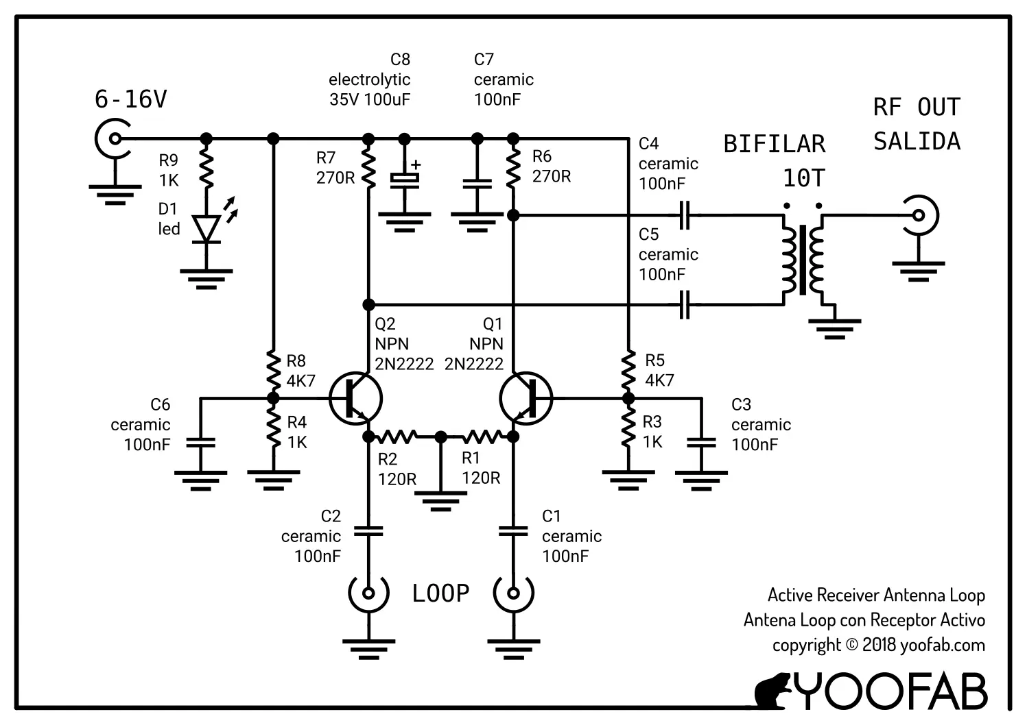
CIRCUIT OPERATION EXPLAINED#
The YML circuit amplifies signals through a special Low Z differential pair amplifier, rejecting common-mode signals and enhancing differential signals. This approach ensures a clear, amplified signal with minimal interference.
AMPLIFIER CHARACTERISTICS#
- Voltage Gain: Approximately 20dB, suitable for a wide range of receivers.
- Balanced to Unbalanced Output: Utilises a transformer for coaxial cable compatibility.
THIS IS A KIT THAT CAN BE ORDERED FROM THE YOOFAB SHOP @ MACROVEND#
SPRAT ARTICLE#
Dedicated readers of the GQRP SPRAT magazine will most certainly have come across Geoffrey David Cowne - M0OOZ's illuminating article on the active aerial loop. Operating predominantly within the magnetic domain of the EM field, this innovation serves as a formidable defence against the relentless onslaught of QRM (Man-made noise). Our daily companions—Ethernet wiring, household appliances like vacuum cleaners, and an array of electrical devices—contribute to the cacophony of electromagnetic interference. Consequently, the noise floor escalates, drowning out weak signals and crippling radio reception.
A solution to this exasperating issue is revealed by journeying into the magnetic domain. While conventional aerials grapple with the electric component of electromagnetic waves, amplifying the interference, especially in urban locales where human activity amplifies the chaos, the magnetic domain offers a sanctuary. Herein lies a peculiar phenomenon: whereas the inverse square law governs field strength in the electrical domain, the magnetic domain seems to operate under its own mysterious law. Though man-made interference is diminished in this realm, it defies conventional measurements and confounds even the most seasoned experts.
THE MAGNETIC DOMAIN MYSTERY#

The inverse square law is a fundamental principle in physics that describes how the intensity of a physical quantity, such as light or sound, decreases as the distance from its source increases. Specifically, it states that the intensity (I) is inversely proportional to the square of the distance \((r)\) from the source:
Where:
- \(I\) will be the intensity
- \(K\) is a constant
- \(r\) is the distance from the source
For instance, in the context of electromagnetic waves, if the intensity of the wave at a distance of 1 metre from the source is 20 units, then at a distance of 3 metres, it would be
However, when we enter into the magnetic domain, a peculiar phenomenon emerges. Despite the intuitive application of the inverse square law, man-made interference seems to diminish at a rate that defies conventional measurements. This enigma perplexes experts and challenges our understanding of electromagnetic phenomena.
One plausible explanation for this anomaly lies in the inherent properties of the magnetic domain. Unlike the electrical domain, where aerials primarily interact with the electric component of EM waves, the magnetic domain operates under different dynamics. The intricate interplay of magnetic fields and their interaction with man-made sources may lead to a suppression of interference, shielding sensitive equipment from the disruptive effects of electromagnetic noise.
While my innovative circuit, featuring a low-impedance input differential amplifier, effectively mitigates noise in the electrical domain, the underlying mechanisms behind the magnetic domain's resilience to man-made interference remain a tantalizing puzzle, ripe for exploration and discovery.
There are theories and hypotheses regarding why man-made interference may be suppressed in the magnetic domain compared to the electrical domain of electromagnetic waves; there isn't a comprehensive, universally accepted explanation.
Our understanding of electromagnetism has advanced significantly over the years, but there are still areas where further research is needed to fully comprehend the intricacies of electromagnetic interactions, especially in complex environments such as urban areas with high levels of electromagnetic interference.
Researchers continue to explore various aspects of electromagnetism, including the behaviour of electromagnetic waves in different domains and their interactions with materials and structures. As our understanding grows and new technologies emerge, we may gain more in-depth insights into phenomena like the behaviour of electromagnetic waves in the magnetic domain and its implications for practical applications such as radio communication.
So, while we may not have a complete understanding of the magnetic domain in this specific context, ongoing research and scientific inquiry contribute to our collective knowledge and may eventually lead to breakthroughs in this area.
ELECTRIC DOMAIN#
- Nature: The electric domain is characterized by electric charges and their interactions. Electric fields are generated by stationary or moving electric charges. The strength of the electric field is directly related to the amount of charge and inversely related to the square of the distance from the charge.
- Sensitivity to Interference: Electric fields can be easily influenced by conductive materials and can induce charges in these materials, leading to potential interference. Electric fields are also more susceptible to interference from man-made sources, such as power lines, electrical equipment, and broadcast signals because these sources often involve moving charges or changing electric potentials.
MAGNETIC DOMAIN#
- Nature: The magnetic domain is defined by magnetic poles and the magnetic fields they generate. Magnetic fields arise from moving electric charges (currents) and the intrinsic magnetic moments of elementary particles. Unlike electric fields, magnetic fields do not act on stationary charges but on charges in motion and on magnetic materials.
- Resistance to Interference: Magnetic fields penetrate most materials without inducing significant currents that would lead to interference, making them inherently less susceptible to man-made noise. This is partly because the materials that significantly interact with magnetic fields (e.g., ferromagnetic materials) are less common in the environment compared to conductive materials that interact with electric fields. Additionally, the generation of interference in the magnetic domain typically requires changing currents, which are less omnipresent in the environment compared to the static and varying electric potentials that affect the electric domain.
CONCLUSION#
The YooFab Active Magnetic Receiver Loop represents a leap in receiving aerial technology, combining innovative design with practical functionality. Ideal for hobbyists and professionals alike, it ensures superior reception in the most challenging environments.
FOOTNOTES#
-
Why 1 MHz to 30 MHz? From experimentation, I felt that going below 1 MHz would only encourage the QRM that we want to avoid; much of the man-made noise is actually below 1 MHz. In fact, the loop electronics will work below 1 MHz. However, it will progressively offer less gain as the frequency diminishes. The 30 MHz upper limit as also not a ceiling; the aerial will go past this point, but again with diminishing gain. ↩
-
Discover the eco-friendly solution for your power needs with the YooFab AAA 9 Volt battery pack. Perfect for devices requiring 9V power, this pack supports rechargeable batteries, offering a sustainable alternative to single-use PP3 batteries. Rechargeables not only reduce waste and environmental impact but also prove to be more cost-effective over time. Embrace a greener choice without sacrificing performance. ↩